Flashing Sonoff Devices with ESPHome — Local Control, No Cloud
Why Flash Them?
Sonoff devices come from the factory running eWeLink firmware that requires a cloud connection to function. Your automations go out to Sonoff’s servers and come back. If their servers go down, or your internet goes down, your devices stop responding. They also collect data about your usage.
Flashing with ESPHome replaces the factory firmware with your own. The device connects directly to Home Assistant on your local network — no cloud, no third party servers, no internet required. Response times drop from seconds to milliseconds and you have full control over exactly what the device does.
This guide covers three Sonoff devices:
- Sonoff SV — low voltage relay board (5-24V DC) — easiest to work with
- Sonoff S20 — UK mains plug adapter
- Sonoff S26R2 — EU/UK mains plug adapter — most challenging
All three use an ESP8266 chip which ESPHome supports fully.
What You Need
Hardware
- DSD TECH SH-U09C USB to TTL Serial Adapter with FTDI FT232RL — approximately £11.50 on Amazon UK. The FTDI chip is important — cheap CH340 adapters can cause problems. The FT232RL is reliable and well supported on Mac, Windows and Linux.
- Jumper wires — the easiest approach is to buy a pack of Dupont jumper wires and cut them up. Strip and tin about 4-5mm of wire on one end. This gives you a female Dupont connector to plug into the adapter header and a tinned wire end to solder to the Sonoff pads.
- Soldering iron and solder
- A computer with Chrome or Edge browser — other browsers do not support the Web Serial API needed for USB flashing
Software
- Home Assistant with the ESPHome app installed — see the foundations guide if you have not done this yet
- ESPHome Web at https://web.esphome.io — used twice during the process
The FTDI Adapter — Set to 3.3V First
The Sonoff devices run at 3.3V. The FT232RL adapter can supply either 5V or 3.3V selected by a jumper on the board. You must set this to 3.3V before connecting to any Sonoff device. Supplying 5V will damage the ESP8266.

Look for the jumper near the bottom of the board labelled 5V / VCC-3V3 — move it to the 3V3 position. Check this every session — it is easy to knock accidentally.
Safety — Read This Before Opening Anything
Never work on these devices while they are plugged into mains power. During the entire flashing process the device is powered only by the 3.3V from the USB adapter via your computer. Keep the mains plug out of the wall for the entire procedure.
The Four Programming Pads
All three Sonoff devices have four pads for serial programming:
| Pad | Purpose |
|---|---|
| VCC or 3V3 | 3.3V power from the adapter |
| GND | Ground |
| TX | Transmit — connects to RX on the adapter |
| RX | Receive — connects to TX on the adapter |
TX and RX always cross-connect — Sonoff TX goes to adapter RX, Sonoff RX goes to adapter TX. This trips up almost everyone at least once. If the flash fails, swap these two wires first.
Soldering Technique
Photograph the PCB before you solder anything. The wires will cover the pad labels and you will need to refer back to them.
Tin the pads on the Sonoff PCB first with a small amount of fresh solder. Tin the stripped wire ends too. Then lay the wire over the pad and apply the iron briefly — the solder flows together quickly with good tinned surfaces.
Solid core wire is easier to work with than stranded — it stays in position. Stranded wire works fine if that is what you have, just tin it well.
Watch for solder bridges and stray wire strands (Careless Whiskers). A stray strand touching an adjacent pad or component will cause problems. After soldering, inspect carefully and remove any whiskers of wire or solder bridges between pads before proceeding.
Sonoff SV — The Easiest
The Sonoff SV is a low voltage relay board for 5-24V DC. It is the most accessible device — no mains wiring to work around, just a bare PCB with clearly labelled pads on the board edge.
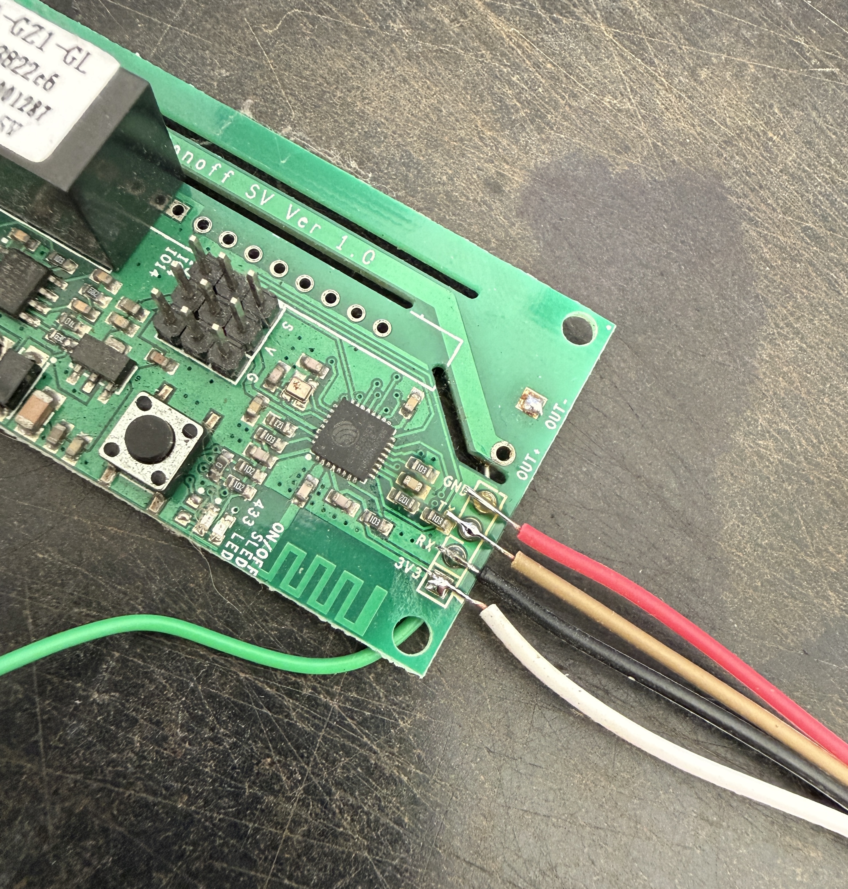
The pads are labelled GND, RX, TX, 3V3 on the board edge. Solder your four wires and connect to the adapter — remembering to cross TX and RX.
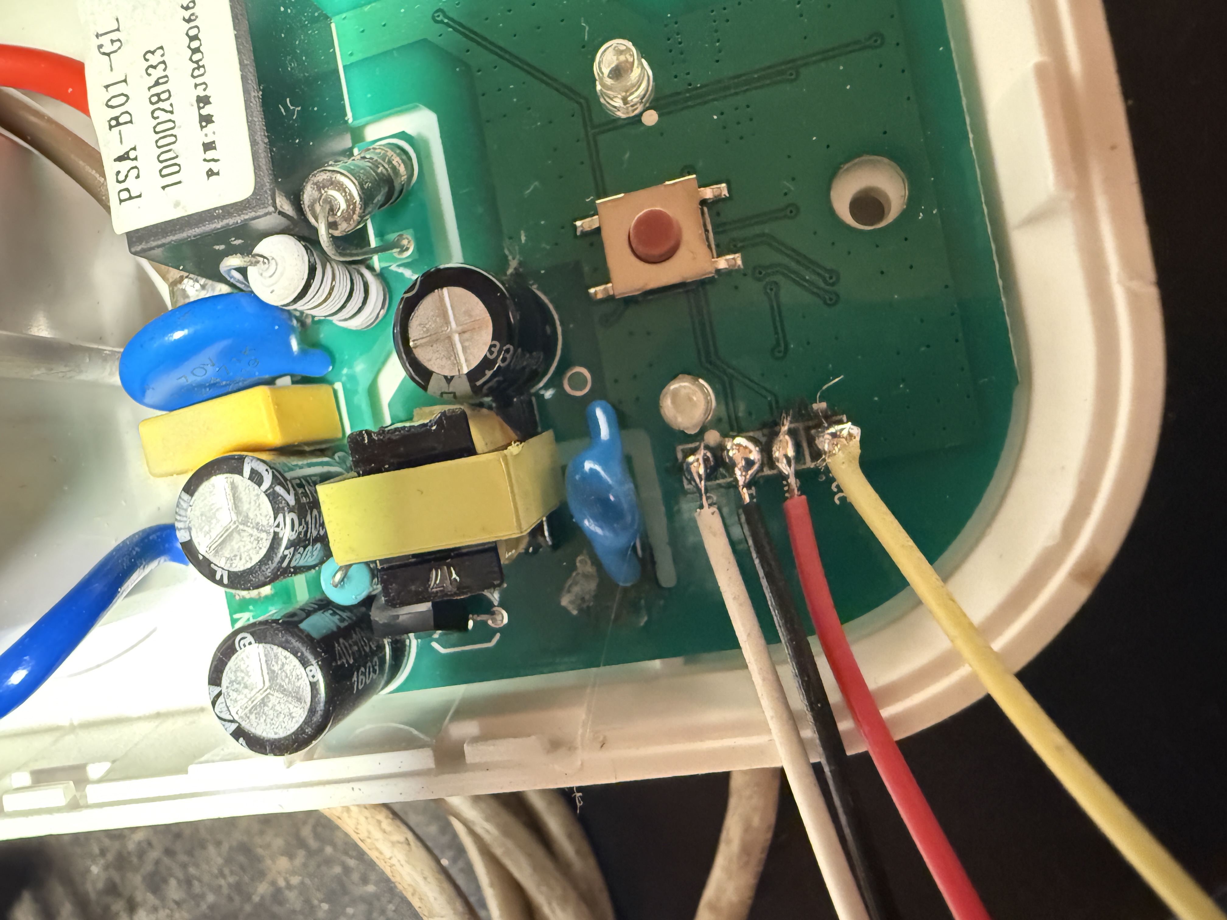
Sonoff S20
The S20 is a UK mains plug adapter. Remove the one screw on the back — the case then splits open. The PCB lifts out and the four programming pads are clearly labelled and well spaced at the bottom of the board.
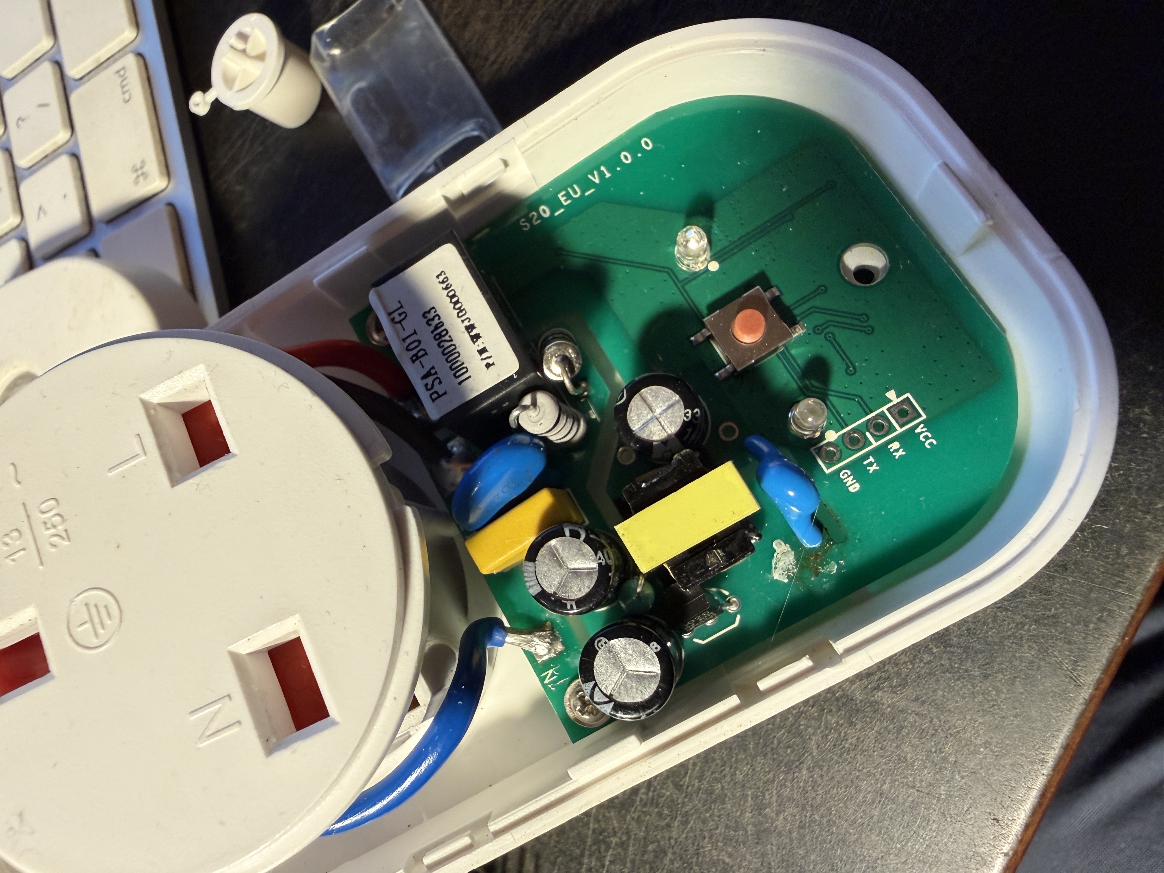
The pads are labelled GND, TX, RX, VCC from left to right. You do not need to lift the PCB out — solder the wires with the board in place in the case.
Sonoff S26R2 — The Most Challenging
The S26R2 requires accessing the reverse side of the PCB. To get there you need to bend the mains wires carefully out of the way so the board can be removed and turned over. Take care not to stress the mains connections.
Once you have access to the back of the board, the pads are smaller than the S20 and require more careful soldering. The other critical difference: the GND pad is physically separate from the VCC, TX and RX cluster — it sits at a different position on the board and is easy to miss entirely.
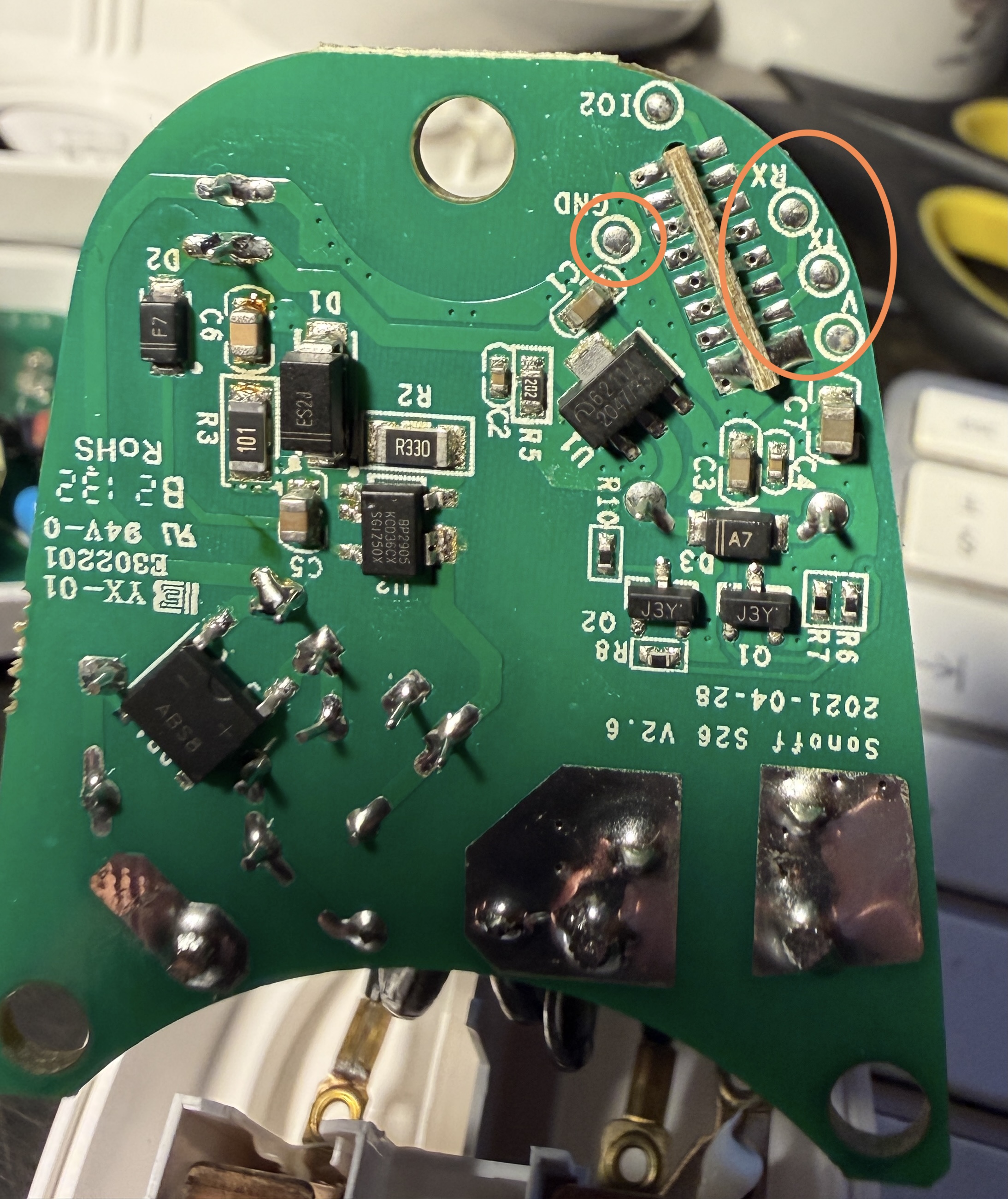
The orange circles in the photo mark the GND pad on the left and the TX/RX/VCC cluster on the right. Solder carefully to the smaller pads.
Flashing Process
This is a two-stage process. ESPHome Web (web.esphome.io) is used twice — once to install a generic ESPHome bootloader, and once to flash your actual configuration. The reason for this is that the initial web flash does not reliably set up WiFi — you need to flash your own yaml which includes your credentials.
Stage 1 — Initial Flash via ESPHome Web
With the Sonoff connected to your adapter but not yet plugged into your computer:
Enter flash mode:
- Hold the button on the Sonoff device (this connects GPIO0 to GND internally)
- While holding, plug the USB adapter into your computer
- Keep holding for a second or two then release
Some Sonoff devices with this chip revision enter flash mode automatically when connected to a programmer — if the flash proceeds without holding the button, that is normal.
Open Chrome or Edge and go to https://web.esphome.io
Click Connect, select the serial device that corresponds to your FT232RL adapter, and follow the prompts to install ESPHome. When it asks for WiFi credentials, enter them — you may be lucky and the device connects to your WiFi successfully at this point, in which case you can skip Stage 3. However with ESP8266 based devices this step frequently fails to connect despite correct credentials. If the device does not appear online in ESPHome after a minute or two, do not worry — proceed to Stage 2 and 3 regardless.
Keep the USB adapter plugged in and leave the web.esphome.io page open.
Stage 2 — Create Your Configuration in the ESPHome App
In Home Assistant, open the ESPHome app.
- Click Add Device
- Click Continue
- Choose Empty Configuration
- Give the device a name — use something unique and descriptive, you cannot easily change this later
- The device will appear in the ESPHome dashboard as offline — this is expected
Click Edit on the new device and paste in your yaml configuration (see the yaml section below). Save it.
Stage 3 — Download and Flash Your Configuration
With your yaml saved, click Install on the device.
Choose Plug into this computer
Choose Download project — this compiles your yaml and downloads a .bin firmware file to your computer.
Now go back to https://web.esphome.io (still open from Stage 1).
Click Install → Choose file and select the .bin file you just downloaded.
Click Install and wait for the process to complete.
The device will reboot with your yaml configuration, connect to your WiFi, and appear as online in the ESPHome dashboard. From this point all further updates are done wirelessly — no USB cable needed.
ESPHome yaml Configuration
Sonoff S20 and S26R2
esphome:
  name: sonoff-s20-1              # Unique name — do not change after first flash
  friendly_name: Sonoff S20 1

esp8266:
  board: esp01_1m

logger:

api:

ota:
  - platform: esphome

wifi:
  ssid: !secret wifi_ssid
  password: !secret wifi_password
  ap:
    ssid: "S20 Fallback"          # Fallback hotspot if WiFi fails
    password: "changeme123"       # Change this to something of your own

captive_portal:                   # Provides a web UI via the fallback hotspot

binary_sensor:
  - platform: gpio
    pin:
      number: GPIO0
      mode: INPUT_PULLUP
      inverted: true
    name: "Button"
    on_press:
      - switch.toggle: relay

  - platform: status
    name: "Status"                # Connectivity sensor in HA

switch:
  - platform: gpio
    name: "Relay"
    pin: GPIO12
    id: relay
    restore_mode: RESTORE_DEFAULT_OFF

output:
  - platform: esp8266_pwm
    id: led
    pin:
      number: GPIO13
      inverted: true

light:
  - platform: monochromatic
    name: "LED"
    output: led
    internal: true                # Hides the LED from HA — it is used internally only
The fallback hotspot is important. If the device cannot connect to your WiFi — wrong password, network name changed, router issue — it will create its own hotspot named “S20 Fallback”. Connect to it from your phone or computer and a captive portal page will appear allowing you to update the WiFi credentials. This means a WiFi misconfiguration never bricks the device.
Sonoff SV
esphome:
  name: sonoff-sv-1
  friendly_name: Sonoff SV 1

esp8266:
  board: esp01_1m

logger:

api:

ota:
  - platform: esphome

wifi:
  ssid: !secret wifi_ssid
  password: !secret wifi_password
  ap:
    ssid: "SV Fallback"
    password: "changeme123"

captive_portal:

binary_sensor:
  - platform: gpio
    pin:
      number: GPIO0
      mode: INPUT_PULLUP
      inverted: true
    name: "Button"
    on_press:
      - switch.toggle: relay

  - platform: status
    name: "Status"

switch:
  - platform: gpio
    name: "Relay"
    pin: GPIO12
    id: relay
    restore_mode: RESTORE_DEFAULT_OFF

output:
  - platform: esp8266_pwm
    id: led
    pin:
      number: GPIO13
      inverted: true

light:
  - platform: monochromatic
    name: "LED"
    output: led
    internal: true
After Flashing — Home Assistant Integration
Once online, the device appears automatically in Settings → Devices & Services → ESPHome in Home Assistant. You will have a switch entity for the relay and a binary sensor for the button.
Build automations, add to dashboards, monitor alongside all your other HA devices — entirely locally with no cloud dependency.
Tips and Lessons Learned
- Photograph the PCB before soldering — the wires hide the pad labels
- Tin pads and wires separately first — then join them
- Check the 3.3V jumper on the adapter before every session
- TX and RX always cross-connect — if the flash fails, swap these two first
- Use cut-down Dupont jumper wires — female end plugs into the adapter header
- The S26R2 GND pad is separate — easy to miss
- Inspect for solder bridges and stray wire strands before powering up
- If no serial port appears — try a different USB cable, different USB port, or check your OS has the FTDI driver installed
- Device name cannot easily be changed — once HA starts recording statistics against an entity ID, renaming creates orphaned data
Questions
If anything here is unclear or you get stuck, get in touch.
Contact: fletcher@gingineers.com